Author Topic: Maximum DC voltage for Series I/II electronics  (Read 446 times)

peter_jonas

  • club
  • Member
  • *
  • Posts: 50
Maximum DC voltage for Series I/II electronics
« on: March 28, 2006, 02:00:50 PM »
Dear Mica,
 
I regularly modify various brands of preamps to provide an integrated power supply for Series basses (See a modified F-1X below).


I find that in most preamps employing solid state (or hybrid) circuitry the required voltages are already present. From a previous post I also understand the optimal supply voltage is about +/- 22 to 25 VDC.
 
Can you please confirm to me what the maximum +/- DC voltage is the Series electronics can use safely. In particular, I have just modified a preamp that has +/- 30 VDC available. Would this voltage still be safe to use?
 
Also, if you don't mind, could you please let me know what the minimum practical (usable votage is)?
 
Thanking you,
 
Peter Jonas

mica

  • alembic
  • Senior Member
  • *
  • Posts: 10595
Maximum DC voltage for Series I/II electronics
« Reply #1 on: March 28, 2006, 05:36:09 PM »
Hi Peter,
 
I talked to my dad about your post. Our recommendation is +/-22VDC maximum (44 volts between the rails), so the +/-30 VDC is uncomfortably high.
 
As far as a minimum practical usable voltage, +/-7 VDC will function.
 
It looks really nice, thanks for helping out the Alembic customers in your area. What's the cable on the right by LED?

peter_jonas

  • club
  • Member
  • *
  • Posts: 50
Maximum DC voltage for Series I/II electronics
« Reply #2 on: March 28, 2006, 07:43:09 PM »
Hi Mica,  Thanks for the info.  Actually, you really got me scared, because last night I was a naughty boy and did try my Series I with this +/- 30 volt supply without asking first. It all worked, and there seems to be no damage, although I admit it was a bit careless. I would not have done it with someone else's bass.  Something seemed to suggest to me that there were local voltage regulators on the Series electronics PCB, and I thought I'd get away with it. Well, I did. That is why I wanted to know the absolute maximum, rather than the recommended voltage.  In any case this F1-x was (is) my first one, and in many respects I have used it as a test bed for various idas I wanted to try.  The connector on the right is a tuner output. It has +9 volt regulated supply voltage and line out taken from the "Pre" position of the original DI output.  Here is what it looks like in close up:  

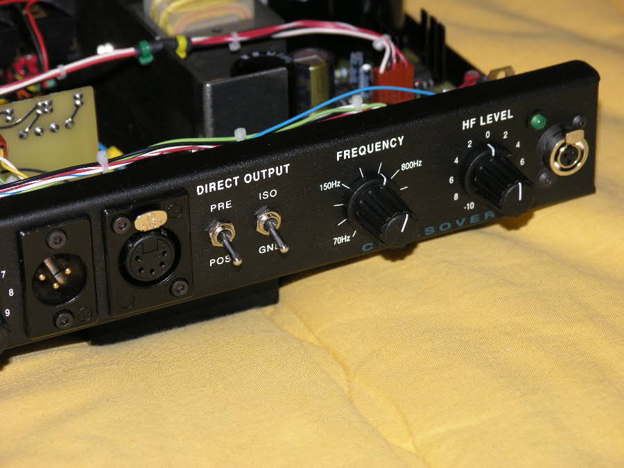
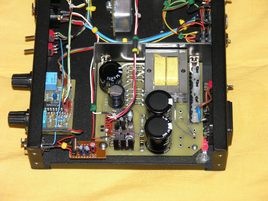
  On the photo below you can see the little local regulator for the 9V supply, and the blue wire going to the Pre/Post switch.  

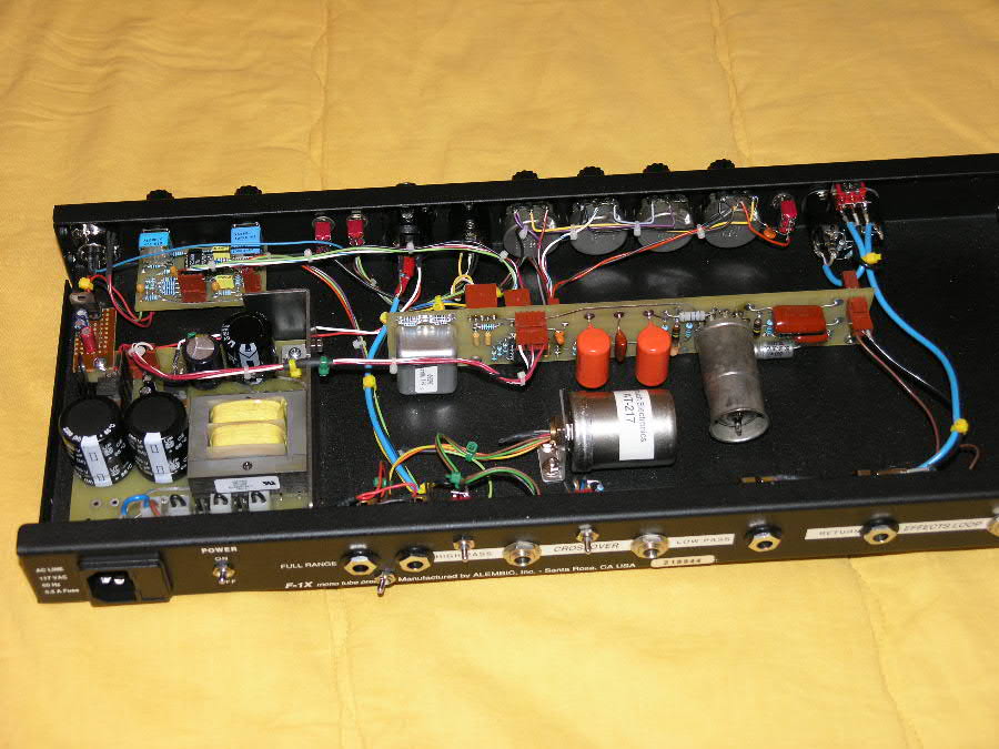
  The shot below shows a few of the other things I have done to this one, including:  - a balancing transformer for the main full range output,  - doubled up main output jacks to enable driving two channel amps without too much fuss,  - ground lift switch to the right and phase reverse switch underneath. This latter is handy when  the main output is used with one of the cross over outputs.  - the DEEP swithch moved to the back (the switch does not get used all that much)  - further to the right there is a line (active) input, which when in use will disconnect the Series input on the fron panel.  - still further to the rignt I have replaced the so often discussed and notorious Effects Loop Return jack, with one that has gold plated contacts, so on the long term it might prove to be more reliable.  - although it cannot be seen here, on the front panel just above the two original input jacks I installed an input selector switch, to select between the original and added inputs.  There are some other beefed up bits here and there, and for the time being it is running quite well.  

  Your equipment is so well thought out, and so beautylully made that it is a constant inspiration. There are special versions of the DS-5R and SF-2 also in the works, but it is too early to talk about those yet.  Thank you for your kind help.  Peter Jonas

lothartu

  • club
  • Advanced Member
  • *
  • Posts: 232
Maximum DC voltage for Series I/II electronics
« Reply #3 on: March 29, 2006, 08:14:11 AM »
Let me be the first to say .. WOW!  
 
Your work looks very clean too. Nice!
 
 
(Message edited by LotharTu on March 29, 2006)

2400wattman

  • club
  • Senior Member
  • *
  • Posts: 885
Maximum DC voltage for Series I/II electronics
« Reply #4 on: March 31, 2006, 08:54:29 AM »
How about some direct outs on the DS-5R w/out modding an F1-X? That would be killer!!

2400wattman

  • club
  • Senior Member
  • *
  • Posts: 885
Maximum DC voltage for Series I/II electronics
« Reply #5 on: April 07, 2006, 01:10:16 PM »
Has this ever been done?(putting d.i.'s on DS-5R)

crgaston

  • club
  • Senior Member
  • *
  • Posts: 640
Maximum DC voltage for Series I/II electronics
« Reply #6 on: April 07, 2006, 05:20:34 PM »
Here's a link to an earlier discussion, Adam.
http://club.alembic.com/Images/402/24871.html?1139725230

jlpicard

  • club
  • Advanced Member
  • *
  • Posts: 416
Maximum DC voltage for Series I/II electronics
« Reply #7 on: April 17, 2006, 08:11:08 PM »
Peter, I'm dying to know what you have in mind for the SF-2 ! Mike

2400wattman

  • club
  • Senior Member
  • *
  • Posts: 885
Maximum DC voltage for Series I/II electronics
« Reply #8 on: April 17, 2006, 08:18:14 PM »
BTW, Peter how is that Peavy amp? Is it worth a damn or not? A 1 space amp that pumps out solid power is so ideal.